PCB Rework Station for Beginners: A Simple Guide to Component ReplacementAuthor : Adrian September 17,gkg solder paste printer 2025Table of ContentsIf you're new to electronics and wondering how to replace components on a printed circuit board (PCB), a rework station is your go-to tool. In this guide, we’ll walk you through the basics of using a PCB rework station for component replacement. Whether you're fixing a faulty part or upgrading a board, this simple guide covers everything you need to know about PCB rework for beginners, including soldering tips and hot air techniques. Let’s dive into the detailed steps, tools, and techniques to help you master rework station basicsand confidently tackle component replacement. From understanding the equipment to practical tips for success, this blog is your starting point for building skills in PCB repair and modification.
What Is a PCB Rework Station and Why Do You Need One?A PCB rework station is a specialized tool designed to help you repair or modify printed circuit boards by removing and replacing components. Unlike a regular soldering iron, a rework station often combines multiple functions, such as hot air for surface-mount device (SMD) components and precise temperature control for delicate work. For beginners, having a rework station is essential because it makes tasks like desoldering and soldering much easier and safer. Rework stations are especially useful for:
For anyone starting with electronics, learning to use a rework station opens up a world of possibilities in repair and design. It’s a must-have tool for tackling component replacementwith precision.
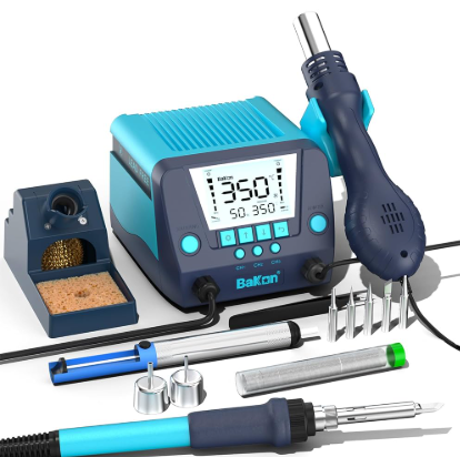
Understanding Rework Station Basics: Key ComponentsBefore diving into a soldering tutorial for beginners, let’s break down the main parts of a rework station. Most beginner-friendly rework stations come with two primary tools: a soldering iron and a hot air gun. Here’s what each does and why it matters. 1. Soldering IronThe soldering iron is used for traditional through-hole components and some SMD parts. It applies heat directly to solder, allowing you to attach or remove components. Look for a rework station with adjustable temperature settings (typically between 200°C to 450°C) to avoid damaging sensitive parts. 2. Hot Air GunThe hot air gun is the star of hot air rework for beginners. It blows heated air to melt solder on SMD components, making it easy to remove or place tiny parts without direct contact. Hot air guns usually have temperature ranges from 100°C to 500°C and adjustable airflow settings (often measured in liters per minute, like 20-120 L/min) to control heat distribution. 3. Control UnitThe control unit is the brain of the rework station. It lets you set and monitor temperatures for both the soldering iron and hot air gun. Some stations also include digital displays for precision, which is great for beginners learning to manage heat levels.
Types of PCB Rework: SMT vs. THTWhen starting with PCB rework for beginners, it’s important to understand the two main types of components you’ll encounter: Surface Mount Technology (SMT) and Through-Hole Technology (THT). Each requires a slightly different approach for replacement. Surface Mount Technology (SMT)SMT components are small and sit flat on the PCB surface. They’re common in modern electronics due to their compact size. Hot air rework is the best method for SMT parts because it evenly heats multiple solder points at once. For example, a typical SMT resistor might have solder pads only 1-2 mm wide, requiring precise heat control to avoid damaging nearby components. Through-Hole Technology (THT)THT components have leads that go through holes in the PCB and are soldered on the other side. These are often larger, like capacitors or connectors. A soldering iron is usually enough for THT rework, though a desoldering pump or wick may be needed to remove old solder. Understanding whether you’re working with SMT or THT components will guide your tool choice and technique during component replacement.
Essential Tools for PCB Rework Beyond the StationWhile a rework station is the core of your setup, a few additional tools will make component replacementsmoother. Here’s what beginners should have on hand:
Having these tools ready will save time and prevent frustration during your first rework projects.
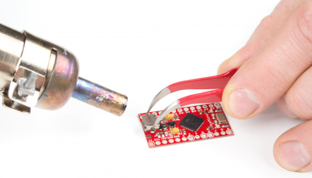
Step-by-Step Component Replacement Guide for BeginnersNow that you’re familiar with the tools and basics, let’s walk through a practical component replacement guide. This process focuses on SMT components using hot air, as they’re common in modern PCBs and trickier for beginners to handle. Step 1: Prepare Your WorkspaceSet up on a heat-resistant mat in a well-ventilated area. Hot air rework produces fumes from flux and solder, so safety is key. Wear safety glasses to protect your eyes from stray solder or hot air. Ensure your PCB is secured, either with a PCB holder or by placing it flat on the mat. Step 2: Identify the Component to ReplaceLocate the faulty or outdated component. If it’s an IC chip, note its orientation (look for a dot or notch indicating pin 1) so you can align the replacement correctly. Use a magnifying glass if needed—SMT parts can be as small as 1 mm across. Step 3: Remove the Old Component with Hot AirSet your hot air gun to a temperature of about 300°C-350°C and a low airflow setting (around 20-30 L/min) to start. Hold the nozzle 2-3 cm above the component and move it in a circular motion to evenly heat the solder. After 10-20 seconds, the solder should melt (it will look shiny). Use tweezers to gently lift the component off. Avoid keeping the heat in one spot for too long to prevent burning the PCB—most boards can only withstand temperatures up to 260°C for short periods. Step 4: Clean the PadsOnce the component is removed, there will likely be leftover solder on the pads. Apply flux to the area, then use a desoldering wick and soldering iron (set to 300°C) to soak up excess solder. The pads should be clean and flat for the new component. Step 5: Place the New ComponentApply a thin layer of solder paste to the pads if working with SMT parts. Position the new component carefully using tweezers, ensuring correct alignment. Double-check the orientation before proceeding. Step 6: Solder the New ComponentUse the hot air gun again at 300°C-350°C to reflow the solder paste. Move the nozzle back and forth over the component for 10-15 seconds until the solder melts and forms a shiny connection. Let the board cool naturally—don’t blow on it, as this can create weak joints. Step 7: Inspect Your WorkCheck the solder joints under a magnifying glass. They should be smooth and shiny, with no gaps or excess solder. Test the PCB to ensure the new component works as expected.
Tips for Successful Hot Air Rework for BeginnersMastering hot air rework for beginnerstakes practice, but these tips will help you avoid common mistakes and improve your skills:
Common Challenges in PCB Rework and How to Overcome ThemAs a beginner, you might face a few hurdles during PCB rework. Here’s how to handle them: 1. Overheating the PCBIf the board starts to discolor or traces lift, you’re applying too much heat. Lower the temperature by 50°C and reduce exposure time. Most PCBs can handle short bursts of heat up to 260°C, but prolonged exposure causes damage. 2. Component MisalignmentIf the new component shifts during soldering, reheat with hot air and reposition it with tweezers. Ensure the solder paste is evenly applied to prevent uneven melting. 3. Excess Solder BridgesSolder bridges happen when too much solder connects adjacent pins. Use a desoldering wick and flux to remove the excess. For tiny ICs with pin spacing as small as 0.5 mm, this is a common issue but easy to fix with patience. Safety Precautions for Using a Rework StationWorking with a rework station involves high temperatures and potential hazards. Keep these safety tips in mind:
Choosing the Right Rework Station for BeginnersWhen selecting a rework station, focus on features that match your skill level and needs. Here are key factors to consider:
Starting with a reliable rework station sets the foundation for successful projects and builds confidence as you learn.
Conclusion: Start Your PCB Rework Journey TodayUsing a PCB rework station for component replacement doesn’t have to be intimidating. By understanding rework station basics, following a clear component replacement guide, and practicing hot air rework for beginners, you can tackle repairs and upgrades with ease. Remember to start small, use the right tools, and prioritize safety as you build your skills. With this guide and a bit of hands-on practice, you’ll be well on your way to mastering PCB rework for beginners. Whether you’re fixing a broken device or experimenting with custom designs, the ability to replace components opens up endless opportunities in electronics. Grab your rework station and get started today! Share · · · · The Role of Flux in PCB Wave Soldering: Selection, Application, and Residue RemovalMarch 16, 2026PCB wave soldering flux types include rosin, water-soluble, and no-clean options with varying activity levels for oxide removal and solder flow. This guide covers selection criteria, spray foam drop-jet application methods, residue removal processes, and alternatives like nitrogen blanketing to boost joint reliability and yields for engineers. Article Achieving Uniform Solder Fillets in PCB Wave Soldering: Process ControlMarch 16, 2026Achieve uniform solder fillets in PCB wave soldering with process control strategies. Optimize flux, preheat, wave height, conveyor speed for consistent fillet shape, height, and wetting balance. Includes visual inspection tips and troubleshooting for reliable through-hole assemblies. Boost quality in production. Article Optimizing Conveyor Speed for Efficient PCB Wave SolderingMarch 16, 2026Learn PCB wave soldering conveyor speed calculation to manage dwell time, immersion depth, and throughput effectively. Electric engineers get practical steps, best practices, and troubleshooting tips for higher process efficiency and fewer defects in wave soldering operations. Article Understanding IPC Standards for PCB Surface Finishes: Ensuring Quality and ComplianceMarch 11, 2026Understand IPC standards IPC 4552 ENIG and IPC 4553 immersion silver for PCB surface finishes. Ensure compliance, enhance solderability, and prevent common defects to achieve reliable, high quality circuit boards. Article High Speed Routing Techniques: PCBMarch 11, 2026Master high speed routing in PCBs to ensure signal integrity and minimize electromagnetic interference. Learn essential techniques for robust designs, from controlled impedance to differential pair strategies. Prevent performance issues and achieve reliable electronics. Article Miniaturization Challenges in PCB AssemblyMarch 11, 2026Navigate the complexities of high density interconnect PCB assembly and precise component placement. Learn to tackle miniaturization challenges, from tiny part handling to thermal stress, ensuring robust and reliable electronics. ArticleGet Instant PCB |